UPCOMING HIGHLIGHT
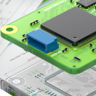
3D Mechatronic Integrated Device Design
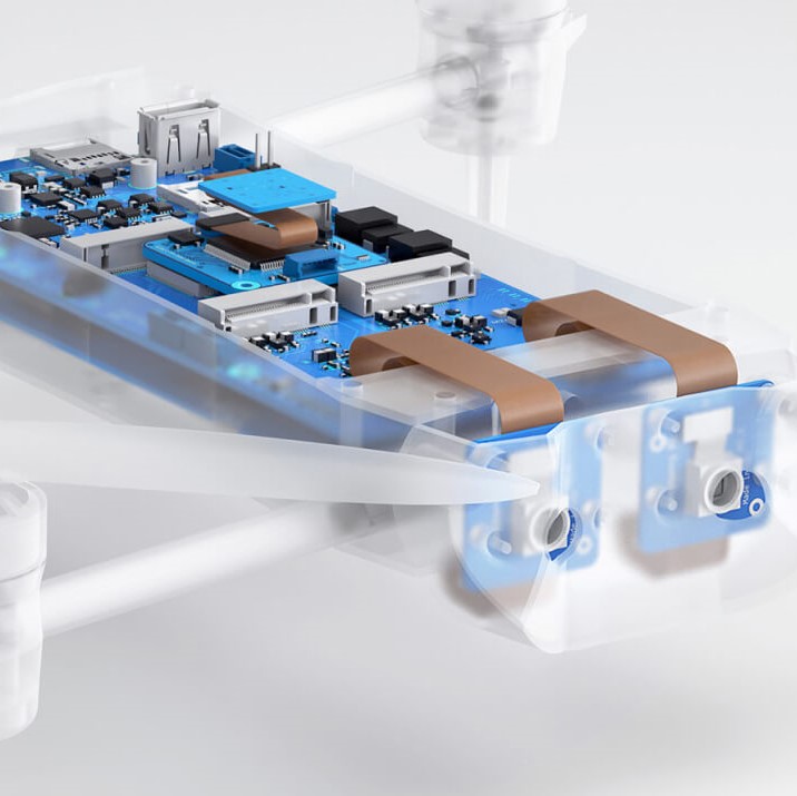
The 3D layout tool for Mechatronic Integrated Device (MID) designs seamlessly merges electronic and mechanical elements, opening up possibilities in diverse fields like wearables, medical devices, and automotive components. The tool simplifies the 3D design process with easy integration, synchronized design, logic-driven layout, and precise placement. It also ensures production-ready data export. The tool is user-friendly, eliminating the need for complex workarounds and making it suitable for the entire 3D-MID design process.
Explore additional upcoming features
See what we're working on, get an insight into what's going on below the
surface and which features you'll be able to take advantage of soon.
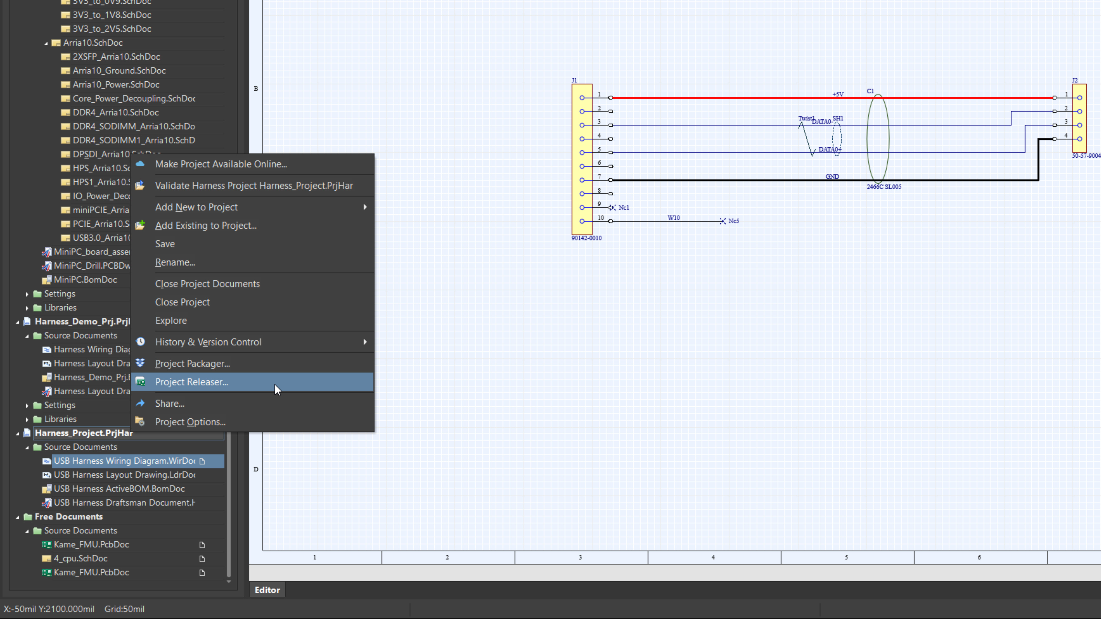
Harness Design Project Releaser
 Available in Closed Beta

The Harness Design Project Releaser streamlines the harness design release process, ensuring reliability and repeatability. With one-touch releasing, users can avoid the risks associated with manual procedures, from snapshotting design files to validation and output generation, all without any manual intervention.
Thank you! We’ll send you an email
when this feature will be available
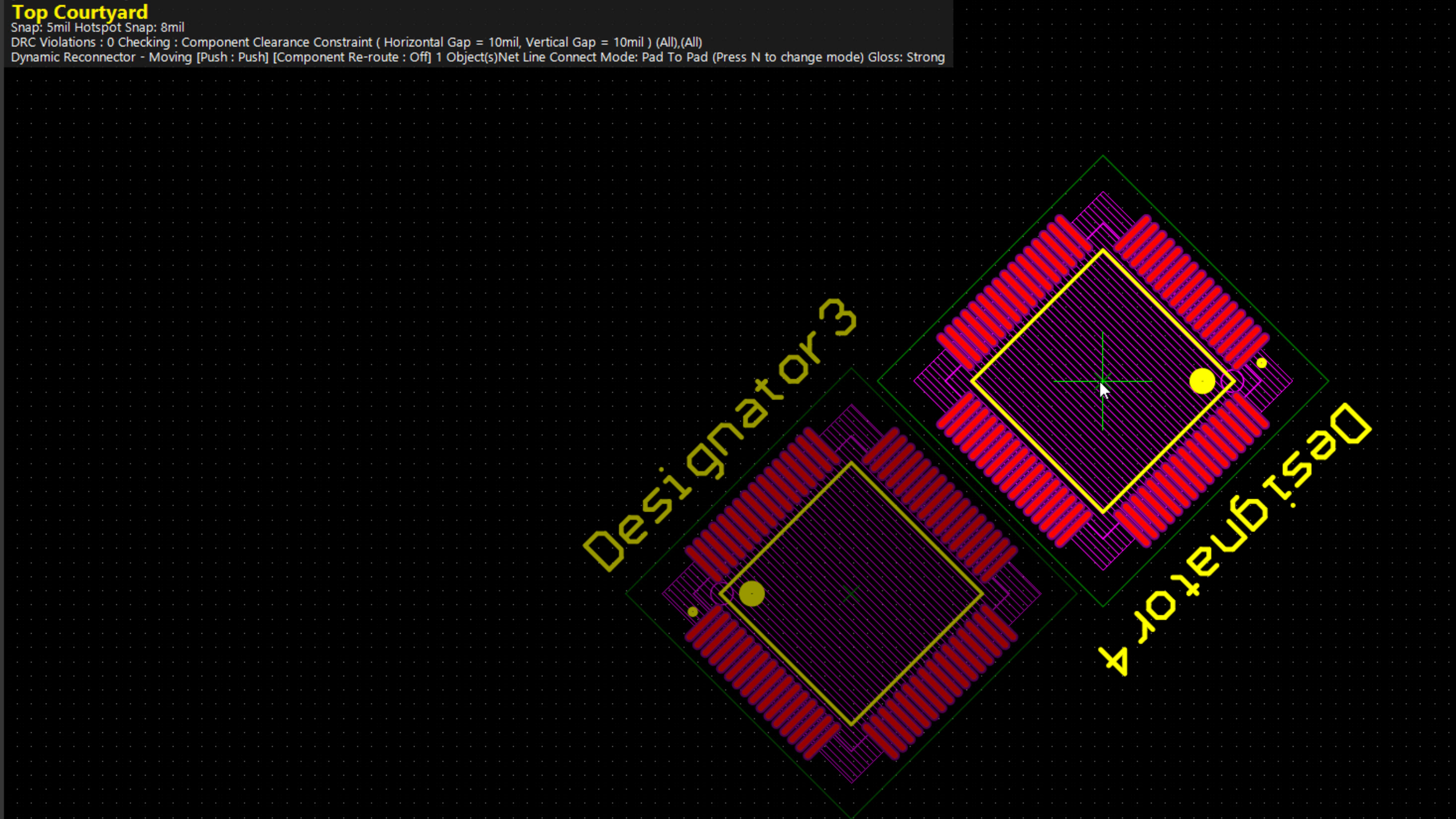
Selection Box for Component 'Push'
 Available in Open Beta

The Selection Box for Component 'Push' enhances user control by observing user-defined geometries for the component selection bounding box during component movement in 'Push obstacles' mode. This helps to precisely manage component placement within specified boundaries, optimizing layout flexibility and accuracy.
Thank you! We’ll send you an email
when this feature will be available
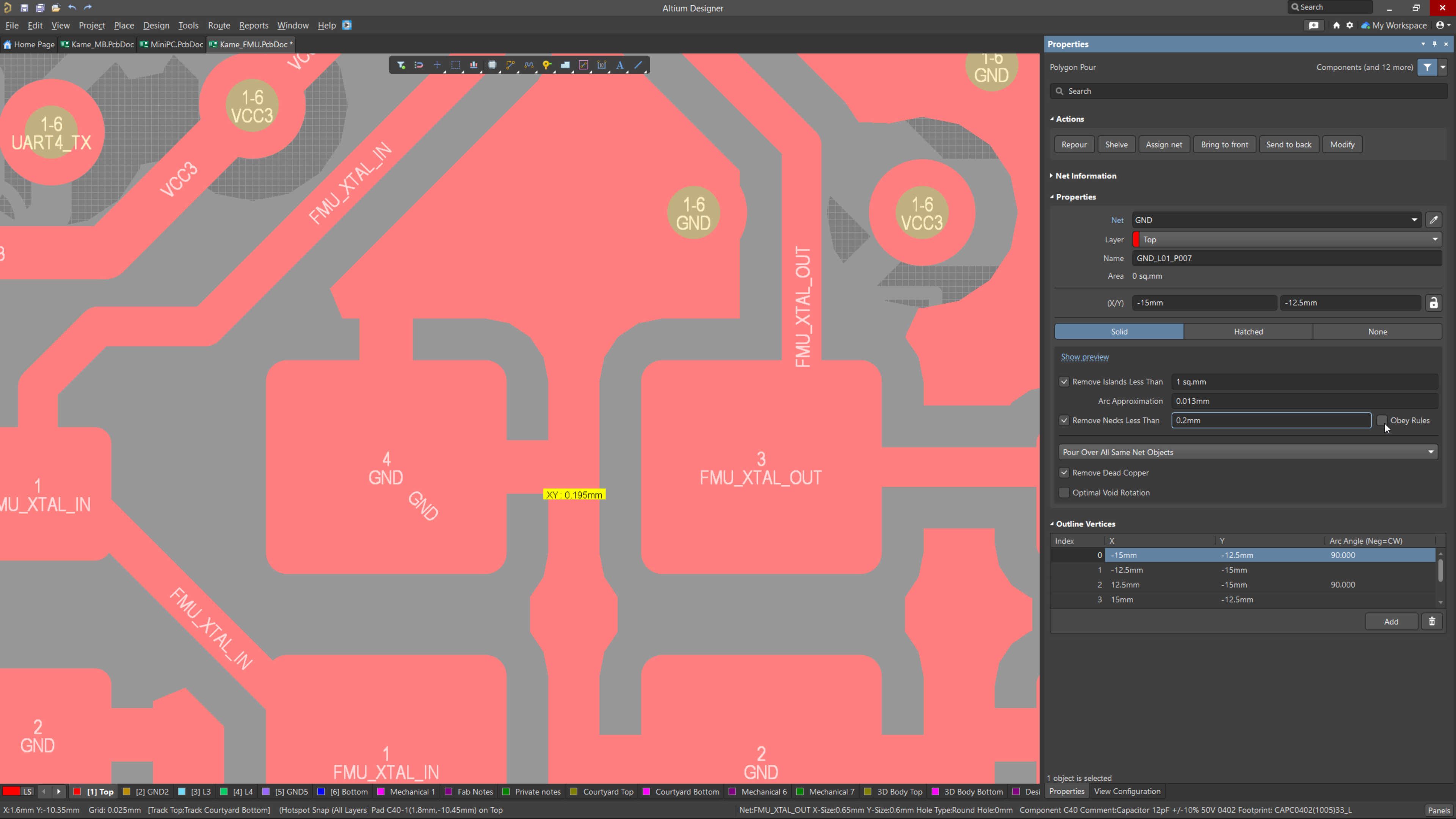
''Obey Rules' Option for Polygon Pour Properties
 Available in Open Beta

The 'Obey Rules' option for Polygon Pour Properties streamlines the removal of narrow necks within solid polygon pours, saving valuable design time. It ensures adherence to design constraints by automatically managing necks narrower than a specified width, simplifying the process of rule compliance.
Thank you! We’ll send you an email
when this feature will be available
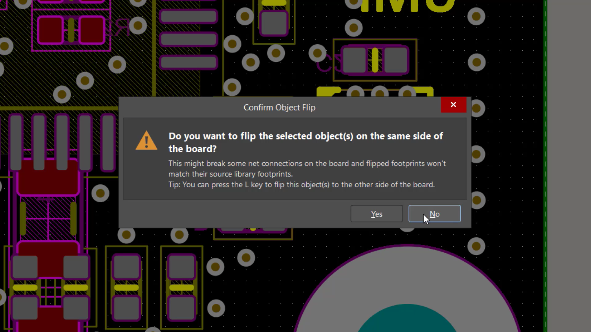
Footprint Mirroring Prevention
 Available in Closed Beta

Footprint Mirroring Prevention adds measures to prevent inadvertent mirroring of a footprint along its X/Y axes, typically the result of having used the associated keyboard shortcuts to mirror a component itself, or the room to which it has been associated. This feature aims to avoid costly board respins that could result from this.
Thank you! We’ll send you an email
when this feature will be available
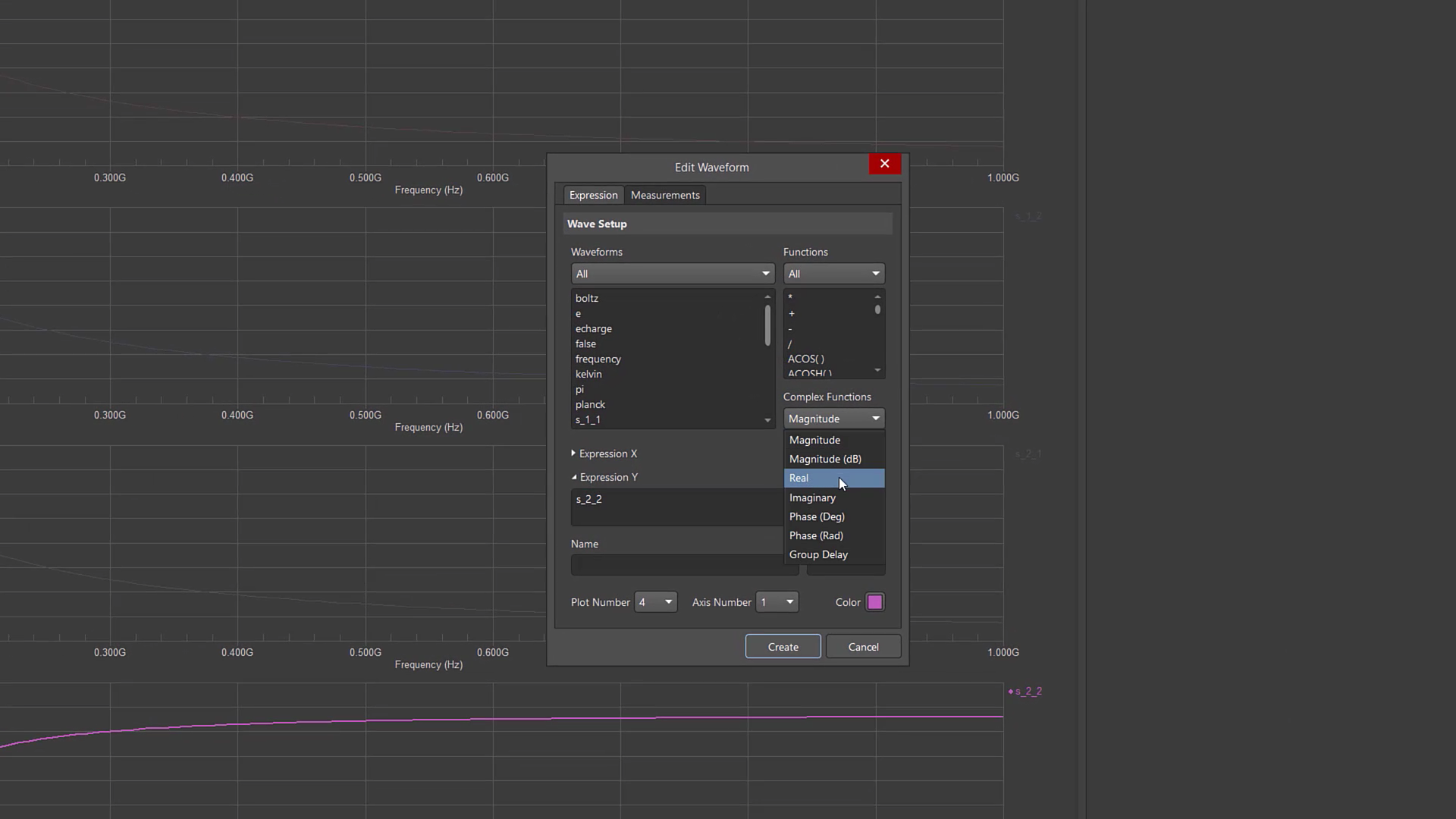
Simulation S-parameters Analysis
 Available in Open Beta

The Simulation S-parameters (scattering parameters) tool facilitates an approach for describing networks based on the ratio of incident and reflected microwaves. These ratios can be subsequently used to calculate the properties of a circuit including input impedance, frequency response and isolation. While this type of analysis is primarily for RF circuits and components, it is equally useful for any circuit with at least two sources (ports). Using S-parameter data as a tool to optimize your design can lead to cost savings, improved product quality, and a competitive edge in the marketplace.
Thank you! We’ll send you an email
when this feature will be available
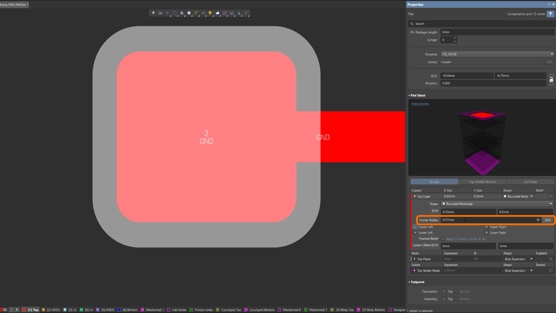
Absolute Value for Pad Corner Radius Chamfer
 Available in Open Beta

The PCB and PCB Footprint editors offer the precise definition of Corner Radius for Rounded Rectangle and Chamfered Rectangle pads as an absolute value, aligned with design measurement units. This feature ensures unparalleled accuracy and consistency in corner radii, enhancing the accuracy of pad shapes.
Thank you! We’ll send you an email
when this feature will be available
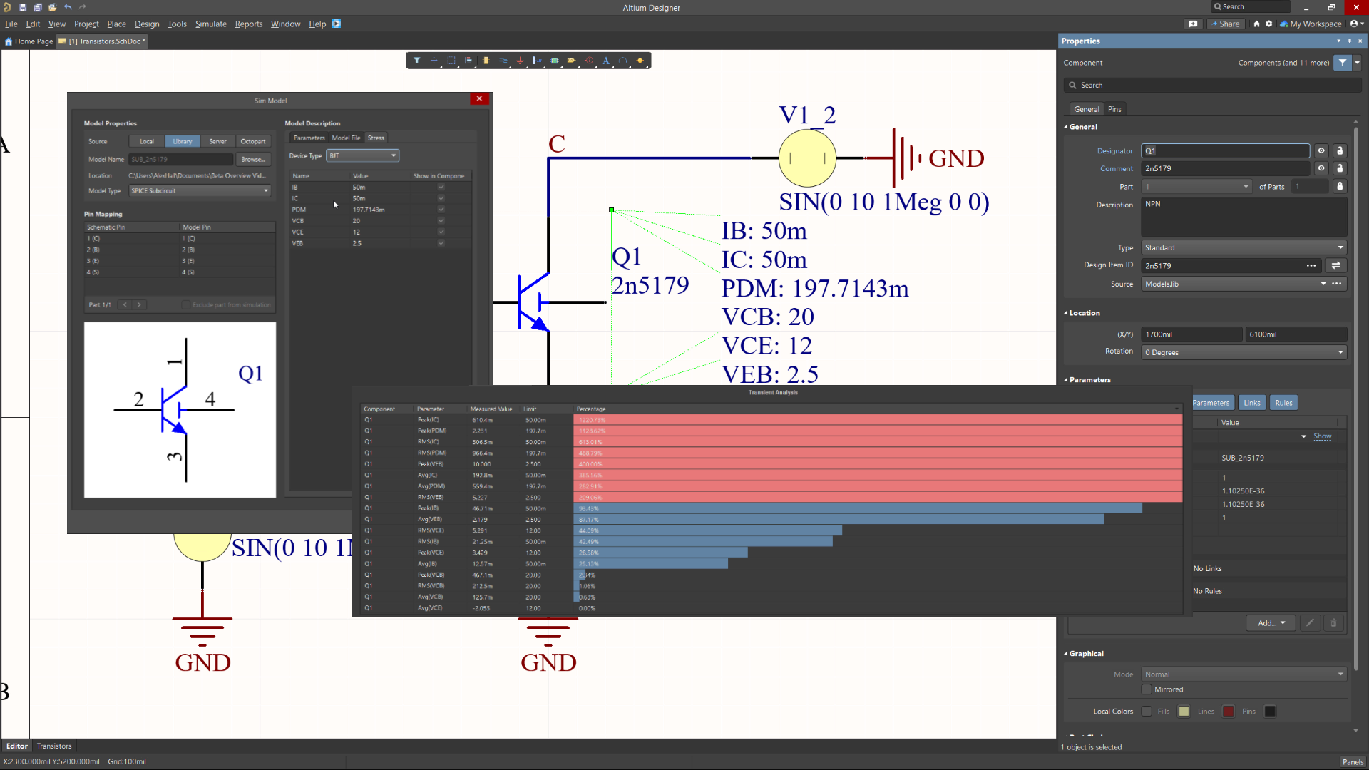
Simulation Stress Analysis
 Available in Open Beta

The Stress Analysis simulation tool computes critical operating conditions like maximum voltages, currents, and power dissipation for components. It examines these conditions against predefined limits specified in a component's stress model, allowing for early identification of potential points of failure. This precision supports the selection of robust components, enhances design efficiency, and minimizes the risk of costly failures, contributing to improved overall design quality and reliability.
Thank you! We’ll send you an email
when this feature will be available

MultiBoard in Draftsman
 Available in Open Beta

MultiBoard Draftsman boosts the efficiency of design reviews and assembly precision by providing a single platform for detailed viewing and paperwork from MultiBoard Designs. By bringing documentation together and allowing a uniform workflow, it not only makes team collaboration smoother but also spots possible design and integration problems early. This tool is crucial for maintaining uniformity, cutting down mistakes, and conserving time and money, thus improving the final products' quality and dependability.
Thank you! We’ll send you an email
when this feature will be available
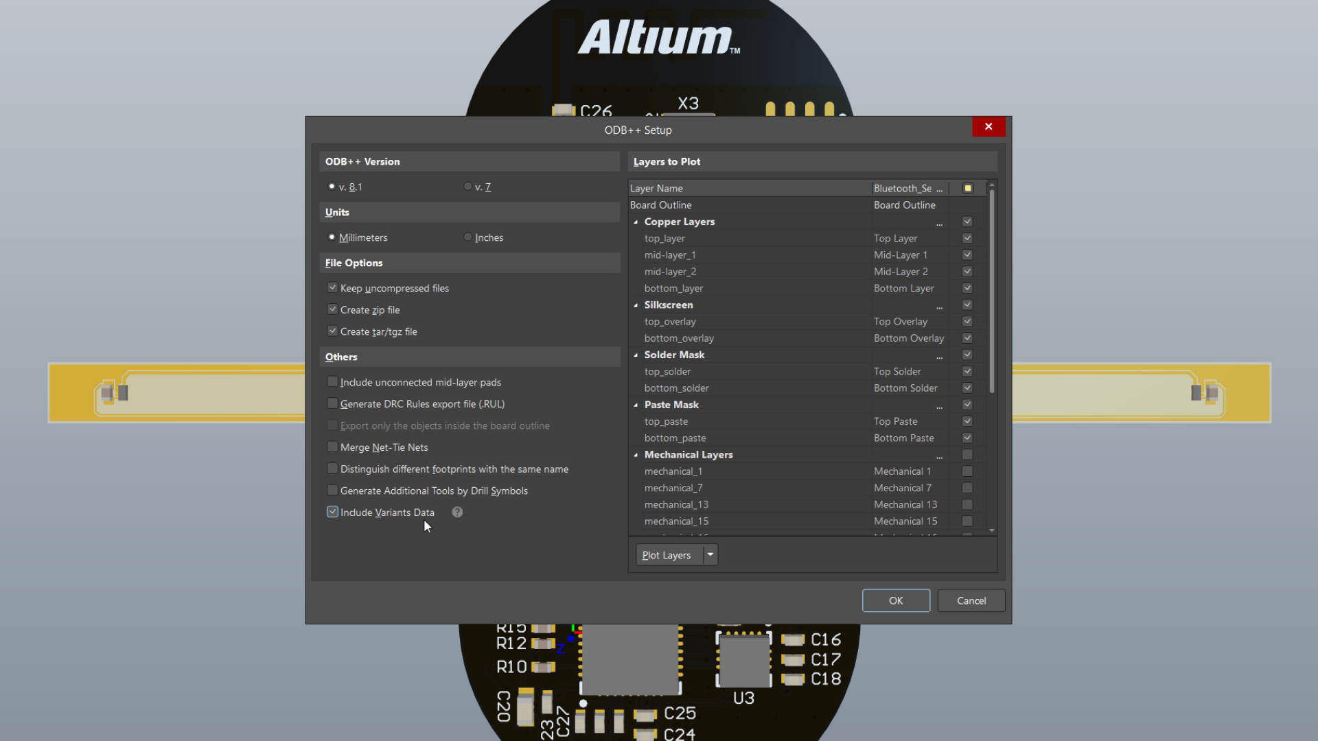
ODB++ v.8.1 support
 Available in Closed Beta

Altium Designer's enhanced ODB++ data generation allows users to choose between the latest v.8.1 and legacy v.7.0 formats within a single installation.
Support for v.8.1 brings a range of highly desirable features and functionality, including Variants support. This allows for the generation of data for all defined variants either collectively in a single instance or separately. It also facilitates Flex/Rigid-Flex manufacturing through the addition of various layer sub-types and implements zones file support, making it easy to distinguish rigid and flex regions of the board.
These improvements ensure a versatile and efficient ODB++ data generation experience, addressing diverse design and manufacturing requirements.
Thank you! We’ll send you an email
when this feature will be available

Subscribe to the newsletter and
we’ll let you know when the
new version is released.
Thank you! We’ll send you an email
when new release will be available.
Be at the forefront of innovative
PCB design technology
Join the Altium Beta Program
Get exclusive access to upcoming features and enhancements while making the tool you use every day even better.
Get Started with Altium Designer
Whether your designs are simple or complex, and you work solo or in a team, Altium has a solution for every engineer or enterprise.

Subscribe for
Feature Release
Already have account? Sign In to Altium Live account
Thank you!
We’ll send you an email when this feature will be available
Subscribe for
Feature Release
Already have account? Sign In to Altium Live account
Thank you!
We’ll send you an email when this feature will be available
Subscribe for
Feature Release
Already have account? Sign In to Altium Live account
Thank you!
We’ll send you an email when this feature will be available
Subscribe for
Feature Release
Already have account? Sign In to Altium Live account
Thank you!
We’ll send you an email when this feature will be available
Subscribe for
Feature Release
Already have account? Sign In to Altium Live account
Thank you!
We’ll send you an email when this feature will be available
Subscribe for
Feature Release
Already have account? Sign In to Altium Live account
Thank you!
We’ll send you an email when this feature will be available
Subscribe for
Feature Release
Already have account? Sign In to Altium Live account
Thank you!
We’ll send you an email when this feature will be available
Subscribe for
Feature Release
Already have account? Sign In to Altium Live account
Thank you!
We’ll send you an email when this feature will be available
Subscribe for
Feature Release
Already have account? Sign In to Altium Live account
Thank you!
We’ll send you an email when this feature will be available


