Interfacing to Other Design Tools

Altium's design software is probably just one of many engineering design environments that you work with, or need to interface to.
Perhaps you need to interface to another design and analysis platform to perform a power simulation, or perhaps you need to import an older design that was developed in another design environment. Whatever the reason, it's likely that one day you'll need to be able to interface to another design tool.
Performing an Import or Export
Interfacing to another design environment is all about transferring design data. That can either be done by reading/writing the design data from/to a different file format, or directly transferring data via software API's.
Import actions are performed via the File » Import command. Also, many of the importers can be accessed via the Import Wizard. Using the Wizard allows related files, such as design files and their libraries, to be batch imported.
Export outputs can be created by adding the required outputs in an Outputjob file (from the Edit » Add Export Outputs sub-menus or from the menus associated with the [Add New Export Output] control, at the bottom of the Export Outputs region, in the main job configuration window) followed by generating the outputs from the file or as part of the Project Release process. Alternatively, export actions are performed via the File » Export menu, in the appropriate editor.
Import Wizard
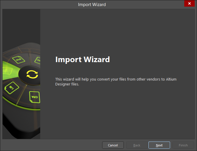
The Import Wizard (File » Import Wizard) will quickly and easily convert your design files from other vendors to Altium Designer files. The Wizard walks you through the import process, handling both the schematic and PCB parts of the project, as well as managing the relationship between them.

- Click Cancel to close the Import Wizard.
- Click Back to navigate to the previous screen.
- Click Next to navigate to the next screen.
- Click Finish to close the Import Wizard. This option is available only on the final page of the Wizard.
Selecting the Type of Files to Import
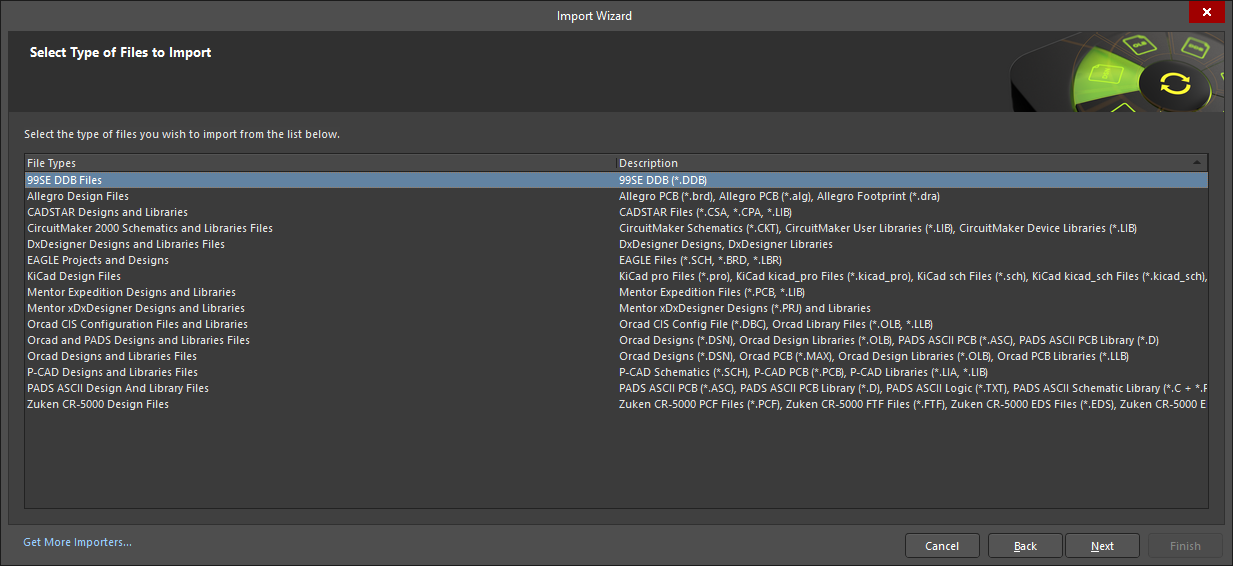
Use this page of the Wizard to select the types of files you want to import. See the Interfacing to EDA Design Tools section below for an overview of types of design files that can be imported using the Import Wizard.
Click Get More Importers to open the Extensions and Updates page from where you can add additional extensions if needed.
The subsequent pages of the Wizard change depending upon the file type you selected. Find the desired file type in the following list then click on the link to access the information regarding that file type.
- 99SE DDB Files
- Allegro Design Files
- CADSTAR Designs and Libraries
- CircuitMaker 2000 Schematics and Libraries Files
- DxDesigner Designs and Libraries Files
- EAGLE Projects and Designs
- Mentor Expedition Designs and Libraries
- KiCad Design Files
- Mentor xDxDesigner Projects and Designs
- Orcad Designs and Libraries Files
- Orcad CIS Configuration Files and Libraries
- PADS ASCII Design and Library Files
- Orcad and PADS Designs and Libraries Files
- P-CAD Designs and Libraries Files
- Zuken CR5000 Design Files
Interfacing to EDA Design Tools
The table below summarizes EDA design tools and their file formats supported for import to and/or export from Altium Designer.
| Name | Supported Formats | Learn More |
|---|---|---|
| Protel® / Altium |
Import Export |
|
| P-CAD® |
Import Export |
Altium Design Software Import-Export Support - P-CAD Design Files Import-Export Support |
| Autodesk® EAGLE™ |
Import (XML format, versions 6.4 through to 9.4) |
|
| Cadence® Allegro® | Import (up to Allegro version 17.4; requires Allegro, check the Import Prerequisites) Allegro binary PCB (*.brd) Allegro ASCII PCB (*.alg) Allegro Footprint (*.dra) |
|
| Cadence® OrCAD® |
Import (up to OrCAD version 17.2) OrCAD PCB Editor (*.brd) (requires the Allegro importer) OrCAD Capture Schematic Library (*.olb) |
|
| KiCad® |
Import (up to KiCad version 6.x) |
|
| LTspice® | Import LTspice ASC Files (*.asc) LTspice ASY Files (*.asy) |
|
| Siemens EDA® DxDesigner® | Import (up to VX2.x) DxDesigner Designs and Libraries |
|
| Siemens EDA® Xpedition™ | Import (up to VX2.x) Xpedition files (*.prj, *.pcb, *.lmc) |
|
| Siemens EDA® PADS™ |
Import (up to VX2.x) Export |
|
| Siemens EDA® xDX Designer® | Import (up to EE7.9.4) xDX Designer Designs (*.prj) and Libraries |
|
| Simbeor® | Export Simbeor file (*.esx) |
|
| Zuken® CADSTAR® | Import (up to 2018 version) CADSTAR Schematic Archive (*.csa) CADSTAR PCB Archive (*.cpa) CADSTAR Part Library (*.lib) |
|
| Zuken® CR-5000® | Import Zuken CR-5000 PCF Files (*.pcf) Zuken CR-5000 FTF Files (*.ftf) Zuken CR-5000 EDS Files (*.eds) Zuken CR-5000 EDF Files (*.edf) Zuken CR-5000 LAF Files (*.laf) Zuken CR-5000 SMB Files (*.smb) Zuken CR-5000 PRF Files (*.prf) Zuken CR-5000 CDFLAF Files (*.cdf) |
Creating a Netlist
Altium Designer supports creation of a netlist, in the indicated format, from all relevant source documents in the active project or from the active source document. The related indexed commands are accessed from the schematic editor, from the Design » Netlist For Project or Design » Netlist For Document sub-menu, respectively.
A Netlist Output, with the indicated Data Source, can also be added to the active Output Job Configuration file by choosing a command from the Edit » Add Netlist Outputs sub-menus or from the menus associated with the [Add New Netlist Output] control, at the bottom of the Netlist Outputs region, in the main job configuration window. Each sub-menu relates to a specific format of netlist, n, while each entry on a netlist format sub-menu relates to a specific Data Source, m.
The following netlist formats are supported:
- Cadnetix
- Calay
- EDIF for PCB
- EESof
- Intergraph
- Mentor BoardStation
- MultiWire
- OrCad/PCB2
- PADS
- Pcad for PCB
- PCAD
- PCADnlt
- Protel2
- Protel
- Racal
- RINF
- SciCards
- Tango
- Telesis
- Wirelist
- XSpice
Depending on the format of netlist you have chosen to create, launching the command will either generate the netlist directly, or an intermediate dialog will appear, allowing you to define specific format-related options. The generated file(s) will initially be closed.
Interfacing to Other Design Tools
Altium Designer can also interface to other design tools (MCADs, CAEs, etc.), for example, using neutral file formats. The table below summarizes other file formats supported for import to and/or export from Altium Designer.
| Name | Supported Formats | Learn More |
|---|---|---|
| Ansoft™ | Export (up to version 4.0) Ansoft™/ANSYS ® Neutral files (*.anf) |
|
| Ansys® | Export EDB files (*.def) |
|
| AutoCAD® | Import/Export (up to version 2018) DXF files (*.dxf) DWG files (*.dwg) |
|
| HyperLynx™ | Export HyperLynx files (*.hyp) |
|
| IDF | Import/Export IDF Board files (*.brd, *.bdf, *.idb, *.enm, *.idf) |
Mechanical Data Import-Export Support - IDF Files Import-Export Support |
| IDX | Import/Export Incremental Design Exchange format files (*.idx) |
Mechanical Data Import-Export Support - IDX Files Import-Export Support |
| Parasolid |
Import Export |
Mechanical Data Import-Export Support - Parasolid Files Import-Export Support |
| SiSoft™ Quantum-SI™ | Export Comma-Separated Values files (*.csv) |
|
| SolidWorks® | Import SolidWorks Part files (*.sldprt) |
Mechanical Data Import-Export Support - SolidWorks Part Files Import Support |
| Specctra® |
Import Export |
|
| STEP | Import/Export STEP format files (*.step, *.stp) |
Mechanical Data Import-Export Support - STEP Files Import-Export Support |
| VRML | Export VRML files (*.wrl) |
Mechanical Data Import-Export Support - VRML Files Export Support |

