Altium 365 Workspace
An integral part of the Altium 365 infrastructure platform, the Workspace is a dedicated server for all your managed content. It facilitates the seamless connectivity of, and the mechanics for moving data between, the design, manufacturing and supply domains. It works harmoniously with Altium Designer to provide an elegant answer to the question of handling design data with secured integrity. The Workspace not only provides solid, secure storage of data, but also enables re-release of data as distinctly separate revisions – essentially tracking design changes over time, without overwriting any previously released data. It also caters for the lifecycle of the data to be managed, allowing people that need to use the data to see, at-a-glance, what stage the data has reached in its 'life' and therefore what it can be safely used for.
The Workspace can accommodate all managed data, including components, domain models, schematic sheets of circuitry and design templates. You can even create and manage your entire design projects directly within the Workspace, with a CAD-centric management view that facilitates collaborative review and commenting of that design, along with inspection of its BOM and history. Through a dedicated Manufacturing Portal you can view and navigate the released file data, inspect the BOM, and view and comment on the snapshot of the design itself; the source for that released data. A chosen release can also be shared – as a Manufacturing Package – directly with your manufacturer.
By furnishing a set of reusable design 'building blocks' within the Workspace you can embark on fresh projects safe in the knowledge that each model, component and higher-order design element has been ratified and approved for use, with no having to reinvent the wheel as it were. The Workspace becomes both the source and destination of design elements, with each new design utilizing elements released to, and managed through, the Workspace. And by designing only with elements from the Workspace, the integrity of those designs is inherently assured.
Server Content Items
Within the Workspace each design entity that can be stored, managed and reused, is represented as a specific type of Item. An Item is uniquely identified within the Workspace and can contain any number of Revisions, where a revision contains the data for that Item. Each time a change is made to the data contained within a revision – which for most Item types can be edited directly within an associated temporary editor – it is committed (or re-released) into a new revision of that Item, meaning that no existing revision can ever be overwritten, and thereby ensuring the highest integrity.
An Item can have any number of revisions, which are essentially an evolution of that Item over time. A change is made and the new data content is committed/uploaded/released into a new revision. The data stored in each revision of an item is therefore typically different. To identify between these different revisions of an Item a revision identifier (ID) is used, which in combination with the Item ID creates a unique identifier for each release of an Item. This gives us the Item-Revision.
Another important aspect of an Item Revision is its Lifecycle State. This is another identifier that can be used to quickly assess what stage that revision has currently reached in its life, and what designers are therefore authorized to do with it. Where the Revision reflects design changes made to the Item, the Lifecycle State reflects the state of the item from a business perspective, such as Planned, New From Design, For Production, Obsolete, and so on.
Direct Editing
The Workspace provides a flexible and secure method of centralizing the storage and management of all types of design data used in Altium Designer. From the schematic model to the component, from managed sheets through to completed PCB designs, the Workspace delivers an ideal method of storing and managing your electronic design data.
Many design entities can be edited and released into the initial revision of a corresponding and newly-created server Item, courtesy of the Workspace's support for direct editing. Direct editing frees you from the shackles of separate version-controlled source data. You can simply edit a supported Item type using a temporary editor loaded with the latest source direct from the server itself. And once editing is complete, the entity is released (or re-released) into a subsequent planned revision of its parent Item, and the temporary editor closed. There are no files on your hard drive, no questioning whether you are working with the correct or latest source, and no having to maintain separate version control software. The Altium Workspace handles it all, with the same great integrity and in a manner that greatly expedites changes to your data.
And at any stage you can come back to any revision of a supported Item in the Workspace and edit it directly by right-clicking on the revision, and choosing the Edit command from the context menu. Once again, the temporary editor will open, with the entity contained in the revision opened for editing. Make changes as required, then commit the release of the document into the next revision of the item.
Components
Altium Designer, with its unified design approach, has traditionally used a component model that extends across all aspects of the electronics design process. However, to seamlessly fit the process of electronics design into the product development process as a whole, this model has evolved by extending to cover other aspects including other design processes (in particular MCAD and Industrial Design), as well as business processes (such as procurement and manufacturing) that intersect with the product development process.
This evolved object model is known as the Unified Component Model.
Under this modeling paradigm the design component, as seen by the designer, is separated from the Manufacturer and/or Vendor parts. This information is not defined as part of the component. Instead, Part Choices are used to map the design component to one or more Manufacturer Parts, listed in a Part Catalog, which in turn can be mapped to one or more Vendor parts. This allows the designer to state, up-front, what real parts can be used for any given design component used in a design.
These components, along with their part choices, are stored in the Workspace. A component is stored as a series of revisions of a uniquely-identifiable Component Item. Each revision is lifecycle-managed, providing collections of certified components authorized to be re-instantiated into new design projects, manufactured into prototypes, or used for production runs. In short, a catalog of components implemented through server-based 'libraries'.
Design Management
The Workspace, in conjunction with Altium Designer, brings support for fully managed projects. Managed projects target the development stage of the project lifecycle and simplify the creation and ongoing workflow for version controlled projects. Centralized storage under the control of the Workspace also enables this feature to be a foundation for other collaborative services.
Some key benefits to using these Workspace-based Projects are:
- Simplified storage. No need to make decisions about storage locations. Backup and other basic services are taken care of.
- Foundation for collaborative features.
- Enforced version control.
- Advantages of a dedicated commenting system.
- Notifications and status. Document status including local modifications is visible to entire design teams.
- Concurrent PCB design works without any complex setup.
- Ability to share the project with multiple people for editing, or for viewing and commenting only.
- Full functionality when using the Project History feature, including VCS-related commit events.
Management is performed through the Projects page of the Workspace's browser interface. New projects can be created through this interface, or through the Create Project dialog in Altium Designer.
You can also access a detailed, CAD-centric view of the project which offers Design, Simulation, Releases, History, and Assembly view options:
- Design – display and navigate source project design documents, view design object properties and place review comments. This view uses the Web Viewer interface to present your design across four distinct data sub-views, to show the source schematic(s), board in 2D, board in 3D and Bill of Materials respectively. This view is for the latest version of the source project data, rather than a specified release from that project, and so could be considered to be a work-in-progress (WIP) view. You can review both the base design and any defined variant thereof.
- Simulation – upload Simulation circuit simulation results files that will be associated with the current project or project Release. The files are effectively attached to the project, which allows members of the Workspace to inspect and/or download simulation results documents that relate to the currently open project
- Releases – view the releases for the project. Access is provided for opening the full release data, or a specific assembly package, which will be presented on a separate tab through a Manufacturing Portal. From this portal you can view and navigate the released file data, inspect the BOM, and view and comment on the snapshot of the design itself; the source for that released data. From either the Releases view, or through the Manufacturing Portal for a specific release, you'll have access to controls for downloading manufacturing data at various levels of granularity (from full data set(s) to individual generated output files). A chosen release can also be sent – as a Manufacturing Package – directly to your manufacturer. You also have the ability to compare Gerber data or Schematic data between releases.
- History – browse a progressive timeline of major events relating to the project including its creation, commits, releases, clones and MCAD exchanges. Each time a supported event happens in association with the project, that event is added to the timeline as a dedicated tile with various actions supported where applicable. For history events, you even have the ability to compare Gerber data between releases or against a locally-generated file set, or compare Schematic data between releases or commits. For more information, see Project History.
- Assembly – work with the interactive Assembly tool to check and progress through the board assembly process. The tool brings togther the project's detailed BOM data and its 2D/3D assembly view to present an interface that provides the required set of graphical and component part information for stepping through the assembly process.
Global Sharing of Manufacturing Package Data
A key aspect of design projects managed within a Workspace is the ability to create and share a release Build Package with others. When shared directly with your manufacturer it can then be thought of as a Manufacturing Package, since it is the package that the manufacturer can browse, download and use to fabricate and assemble the board.
Supporting the ability to share such a package with others and with your manufacturer (who is typically outside of your organization), the Altium 365 Platform provides a dedicated Manufacturing Package Viewer – an element of the platform's Global Sharing support – which allows others to view a manufacturing package from any web browser – anywhere in the world – but outside of your Workspace, so that your designs themselves, and other valuable IP, are kept off limits.
Each shared user will receive an email invite with a link to view a manufacturing package through the Manufacturing Package Viewer. Shared manufacturing packages are presented on the Shared with Me page of the Altium 365 Platform Interface.
The Manufacturing Package Viewer itself allows key stakeholders – and primarily the manufacturing personnel – to see a summary overview of the design, with key board data. Fabrication, Assembly and BOM data sub-pages of the viewer are also provided.
Ultimately, the manufacturing personnel can download a Build Package of the release they have viewed – and from any page of the Viewer – with which to get that revision of the board physically realized.
ECAD-MCAD CoDesign

Most electronic products that are designed are fixed to some kind of mechanical structure, such as a chassis or enclosure. Finding a mechanical conflict between the board (ECAD) and chassis/enclosure (MCAD) late in the design process can be a costly experience. And while you could get a 3D model exported from Altium Designer, it is a manual process that needs a conscious decision and action to do so. In reality, this is performed very infrequently, with the result being that the MCAD designer is never quite sure if what they've got is the latest and greatest. It really shouldn’t be so hard to ensure you’re not about to waste a pile of money just because your tools don’t talk.
The Workspace facilitates native ECAD to MCAD collaboration where data flows seamlessly between domains. No more polling for updates, and no more uncertainty. Data is pushed between domains as the design evolves, ensuring design coherence.
The following MCAD platforms are supported when using the latest Altium CoDesigner plugins:
- Dassault Systemes SOLIDWORKS®
- Autodesk Inventor Professional®
- PTC Creo Parametric®
- Autodesk Fusion 360®
- Siemens NX®
The versions of MCAD tools officially supported will depend on the version of Altium CoDesigner plugin being used (see the New in CoDesigner page).
Component Synchronization
The Workspace facilitates the uni- or bi-directional synchronization of component data with your enterprise systems. A configuration file allows you to specify the direction of synchronization and therefore which parameters are mastered in which system. Component data synchronization between the Workspace and the target enterprise system uses a built-in synchronization process which may be manually triggered or set as a timed repeating event.
The Workspace currently provides direct support for component synchronization to the following enterprise systems:
- PTC Windchill® PLM
- Arena® PLM
Interface configuration is performed through the Workspace's browser interface, with the connection setup and parameter mapping defined within an XML-based configuration file (uploaded to the server). Base configuration files for both supported systems are available to get you started.
When the synchronization process first adds a component's data in the target system, the generated item number is passed back to the component in the Workspace as a PlmPartNumber parameter. This acts as the key parameter when synchronizing data between the Workspace and the enterprise system instance. In addition, the configuration can be arranged so that item parameters/attributes on the enterprise system side will update properties in the Workspace (configurable per field), without having to formally release a new revision of that Component Item.
► See PLM Component Synchronization for more information.
Part Source Configuration
Each Workspace has its own dedicated Part Catalog. This is a managed part catalog database, dedicated to the management and tracking of manufacturer parts and their associated supplier parts. The catalog works only with the Workspace.
The Part Catalog stores items representative of actual Manufacturer Parts, along with one or more items representative of Supplier Parts – the incarnations of those Manufacturer Parts, as sold by the Suppliers/Vendors. Each Supplier Part is a reference to an item in a parts database – either the aggregate parts database of the Altium Parts Provider (which itself interfaces to, and gathers the parts from, enabled Suppliers), or a linked local parts database.
Which Suppliers are actually used – a list of Approved Suppliers – is managed by the Workspace, through the Admin – Part Providers page of its browser interface. This facilitates centralized supply chain management, with designers across the entire organization using the same approved list of Suppliers, with which to source supply chain intelligence for parts used in their designs.
Data Acquisition
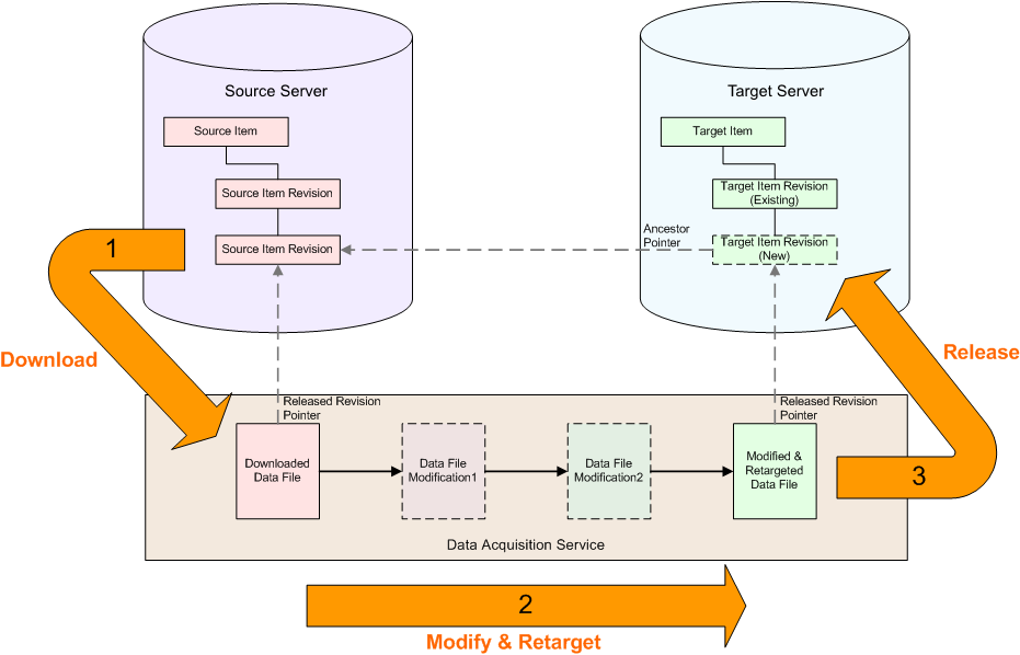
Altium facilitates the ability for an organization to copy the content they need from a source server, and deliver it to a second target server – a process referred to simply as Server Data Acquisition. By acquiring design content, ownership is placed firmly in the hands of the receiving organization, who are free to make modifications and maintain the content – in their Workspace – as they desire moving forward. And by keeping a link between the acquired data and its original source, intelligent handling of the data can be performed, including notification when the source of any copied content is updated. And no matter if additional releases have been made to an item in the Workspace, there is always the possibility to revert to a previous revision from the source server – all by keeping a link back to the item's original source, or Origin.
Acquisition is performed using the Content Cart dialog. Access to this dialog is made from within the Explorer panel. While browsing the source server from which you wish to obtain data, right-click on the revision of a supported Item type that you wish to acquire (or a folder of components, for example), and choose the Operations » Add to Content Cart command from the context menu.


